
基于坡印廷矢量的地震照明分析
作者简介:庞新明(1990—), 女, 黑龙江省绥化市人, 博士在读, 主要从事海洋地球物理研究。E-mail: xmpang@scsio.ac.cn
收稿日期: 2016-09-02
要求修回日期: 2016-10-10
网络出版日期: 2017-06-01
基金资助
国家基金项目(91428204、41376063、41176053)
Seismic illumination analysis based on the Poynting vector
Received date: 2016-09-02
Request revised date: 2016-10-10
Online published: 2017-06-01
Supported by
Natural Science Foundation of China (91428204, 41376063, 41176053)
Copyright
基于坡印廷矢量分解波场、高斯加权去噪, 以及在三维模型定向照明中的测试研究, 可以促进基于坡印廷矢量地震照明方法的推广应用。在目标区通过反向照明分析得到了采集参数最优范围; 根据坡印廷矢量定向分解波场, 统计不同照明角度对应的能量分布情况, 得到最优照明角度范围; 并通过高斯加权去噪, 提高了波场分解的分辨率与保真度, 证明了这种方法的有效性。该方法相比较于传统的射线追踪照明避免了高频近似, 相较于单程波照明波场信息更加全面, 相较于频率域的波场角度分解计算更加简单高效, 加入加权去噪后, 角度分解的波场信息信噪比和保真度均有提高。在三维模型中, 该方法实现了倾角照明和方位角照明。试算结果不仅为复杂的二维地质模型中地震采集设计提供了科学依据, 同时为今后在三维模型中采集参数优化提供了实践经验, 拓展了坡印廷矢量的应用范围。
庞新明 , 赵明辉 , 张敏 , 杨国权 . 基于坡印廷矢量的地震照明分析[J]. 热带海洋学报, 2017 , 36(3) : 86 -93 . DOI: 10.11978/2016082
Research on seismic wave field decomposition and Gaussian de-noising and directional illumination in three- dimensional (3D) models will promote a wide application of seismic illumination based on the Poynting vector. In this paper, optimal angle illumination is found through obtaining the acquisition parameter by laying source in the target area, namely reversed illumination, then decomposing the wave field transmitting from best source position based on the Poynting vector, and using statistics on the energy of different angles. In addition, the de-noised wave filed obtained by Gaussian filter improves the stability and fidelity of wave field decomposition, which demonstrates the effectiveness of the method. Compared to the traditional ray-tracing illumination, illumination based on double way wave equation avoids high frequency approximation, whose information of wave field is more comprehensive compared with one-way wave equation and whose calculation is more efficient. With weighted de-noising, the fidelity and signal-to-noise ratio of the wave field are improved. Moreover, the method is developed in the 3D model to realize dip illumination and azimuth illumination. These results not only provide scientific basis for seismic observation system of complex 2D geological model, but also offer a base for future applications in optimization of 3D acquisition parameters, which is advantageous to promote applied domain of the Poynting vector.
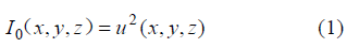
 表示空间点(x, y, z)的照明度(单位: W•m-2);
  表示波场在空间点(x, y, z)的振幅值(单位: N•m-2)。考虑整体观测系统对地下模型的总照明度如公式(2):
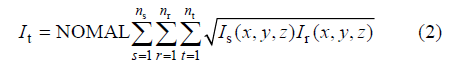
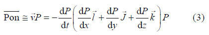
 为坡印亭矢量(单位: W•m-1);
  为速度矢量(单位: m•s-1); P{Invalid MML}为声波应力(单位:N);
  为x轴正方向的单位矢量;
  为y轴正方向的单位向量;
  为z轴正方向的单位向量。
 和空间导数
和空间导数 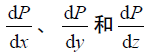 , 代入公式(3)得到坡印廷矢量
  , 坡印廷矢量的方向表征地震波能量传播的方向, 也就是照明方向。在二维情况下, 用坡印廷矢量与垂直方向的夹角作为照明的传播方向; 在三维情况下, 坡印廷矢量的方向与垂直方向为倾角, 坡印廷矢量在水平面的投影与水平方向的夹角作为方位角, 由此得到了表征照明的方向。由公式(2)和(3)分别得到了照明能量的强度和方向。
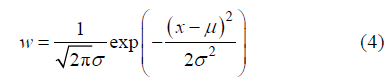
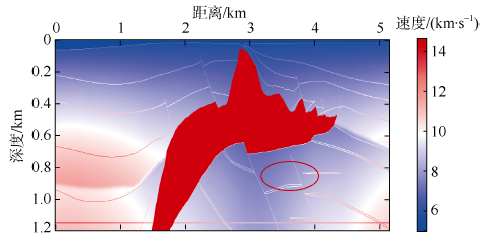
Fig. 1 The salt dome model. The red circle is the target area图1 盐丘模型, 红色圆为目标区 |
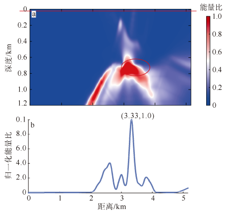
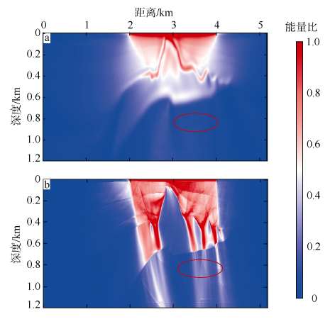
Fig. 2 Reversed illumination of the target area. (a) The energy distribution about reversed illumination; (b) surface energy distribution of reversed illumination (corresponding to the red line in |
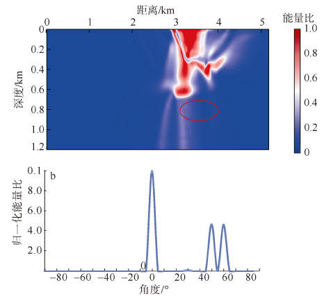
Fig. 3 Illumination of different directions in the target area when placing the source at 3.33 km. (a) Normalized energy distribution; (b) quantized energy distribution of different directions in the target area based on the Poynting vector (corresponding to |
Fig. 4 Illumination energy from 2 km to 4 km of salt dome model. (a) Total illumination energy of 200 sources; (b) illumination energy when the plane angle is changed from 45 to 65图4 盐丘模型2km到4km的照明能量图^a. 200炮的总照明度; b. 平面波45°到65°时照明能量分布图 |
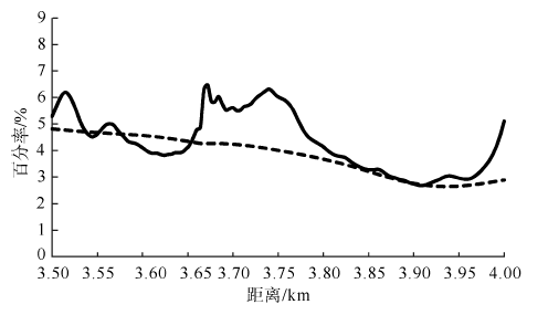
Fig. 5 Comparison of percentage of illumination energy in the target area before and after angle optimization. The dash line and solid line correspond to the illumination energy in |
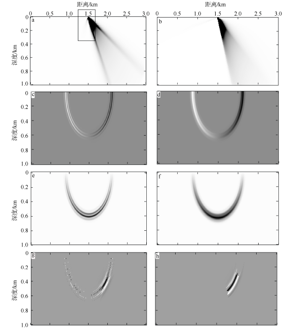
Fig. 6 Comparison of results before and after adding Gaussian weight. (a) and (b) show one source illuminations from 30 to 60 (the black rectangular shows the noise); (c) and (d) show horizontal component; (e) and (f) show vertical component; (g) and (h) show wave snapshots extracted from 30 to 60 angles, before and after adding Gaussian weight, respectively图6 高斯加权前后的对比图^a和b分别是应用高斯加权前后的30°~60°的单炮照明图(图中黑色矩形框内是噪音干扰); c和d分别是应用高斯加权前后的水平分量; e和f分别是应用高斯加权前后的垂直分量; g和h分别是应用高斯加权前后30°~60°的波场快照图 |
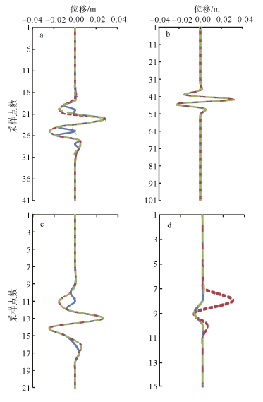
Fig. 7 Comparison of three kinds of waveforms among different transmitting angles, in which the red line represents the waveform extracted from a complete wave snapshot; a blue line represents the waveform extracted from directional composition wave field between 30 and 60; and an olive green line represents the waveform added Gaussian weight based on the blue line. (a), (b), (c), and (d) are waveform comparison when angle=60, angle=45, angle=35, and angle=30, respectively图7 不同传播角度的3种波形对比^a. 60°时的波形对比; b. 45°时的波形对比; c. 35°时的波形对比; d. 30°时的波形对比。红色线段代表从完整的波场分布中抽取的波形; 蓝色线段代表从定向分解的30°到60°的角度波场中抽取的波形; 橄榄绿色线段代表从加入高斯权重的30°到60°定向分解的波场中抽取的波形 |
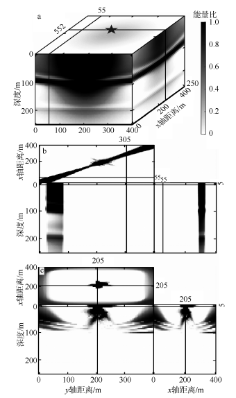
Fig. 8 Directional illumination based on the three- horizontal-layer model. (a) one source illumination when the black star represents the seismic source; (b) directional illumination of one source when the azimuth angle is fixed; (c) directional illumination of one source when the dip angle is fixed图8 三层水平层状模型方向照明图^a. 单炮照明图, 黑色五角星是震源的位置; b. 方位角固定的单炮照明图; c. 倾角固定的单炮照明图 |
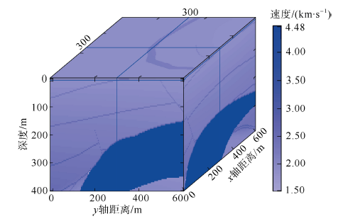
Fig. 9 Three-dimensional velocity model of a salt dome图9 三维盐丘速度模型 |
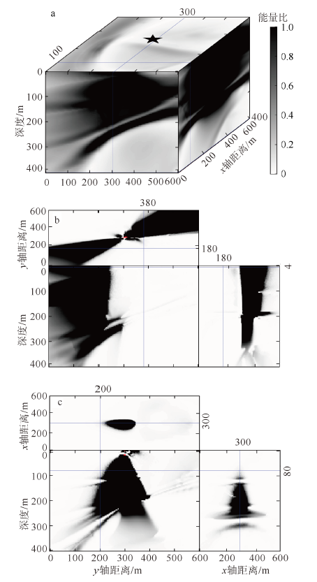
Fig. 10 Three-dimensional directional illumination of a salt dome. (a) One source illumination based on the three- dimensional model of a salt dome. The black star represents one seismic source; (b) Directional illumination of one source when the azimuth angle is fixed; (c) Directional illumination of one source when the dip angle is fixed图10 三维盐丘方向照明^a. 盐丘模型的单炮照明图, 黑色五角星是震源的位置; b. 方位角固定的单炮照明图; c. 倾角固定的单炮照明图 |
The authors have declared that no competing interests exist.
| [1] |
|
| [2] |
|
| [3] |
|
| [4] |
|
| [5] |
|
| [6] |
|
| [7] |
|
| [8] |
|
| [9] |
|
| [10] |
|
| [11] |
|
| [12] |
|
| [13] |
|
| [14] |
|
| [15] |
|
| [16] |
|
| [17] |
|
| [18] |
|
| [19] |
|
| [20] |
|
| [21] |
|
| [22] |
|
| [23] |
|
| [24] |
|
| [25] |
|
/
| 〈 |
|
〉 |
