
Journal of Tropical Oceanography >
Geophysical characteristics and favorable occurrence signs of marine sand-gravel body in Taiwan banks*
Copy editor: YIN Bo
Received date: 2020-09-17
Request revised date: 2020-12-14
Online published: 2021-01-06
Supported by
Project of China Geological Survey(DD20201175)
National Key Research and Development Project(2017YFC0307402)
Copyright
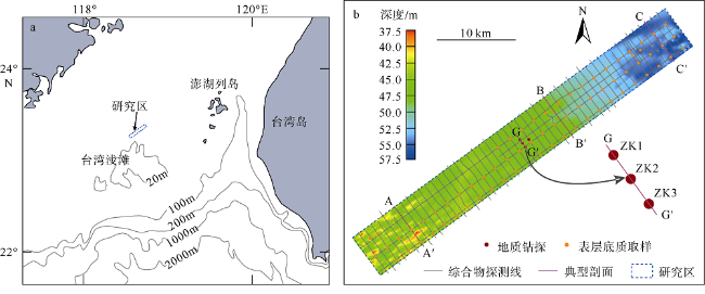
An efficient and economical exploration of the distribution and resources of marine sand is of great significance to social and economic development and marine mineral resources planning. Multi-source geophysical data acquired in Taiwan banks, such as single beam sounding, side-scan sonar, sub-bottom profile, and single-channel seismic, were used to identify the geomorphic signs favorable to the occurrence of marine sand and gravel, such as submarine sand ridges, sand waves, and buried ancient channels, and the signs unfavorable to the occurrence of marine sand, such as thick argillaceous overlying strata. These geomorphic signs alternate progressively on the plane. Comparison of geophysical data with surface sediments and borehole cores shows that the sub-bottom profile can effectively distinguish the upper surface sand-gravel body and thick argillaceous overlying strata (thickness > 10 m). The upper surface sand-gravel body on the sub-bottom profile shows discontinuous reflection with medium or weak amplitude. The single-channel seismic profile can effectively identify the sand-mud interface, and depict the shape of the surface and buried sand-gravel body vertically; and the main characteristic of the sand-gravel body on the single-channel seismic profile is weak amplitude reflection with poor continuity mixed with blank and disordered “white cloud” reflection. The seismic response characteristics of the sand-gravel body reflect that the sand-gravel body is difficult to penetrate, and may also be due to the gas contained in the sand-gravel body. Our analysis shows that when the shape of the sand-gravel body is changeable or the distribution density of boreholes is low, the use of geophysical method combined with a certain number of borehole core constraints, compared with relying on a large number of borehole cores only, can more economically and efficiently make a fine depiction of the vertical shape and plane distribution of sand-gravel body, which is conducive to more accurate estimates of sea sand resources.
LI Yonghang , JIA Lei , NI Yugen , HE Jian , MU Zelin , WEN Mingming , SHAN Chenchen . Geophysical characteristics and favorable occurrence signs of marine sand-gravel body in Taiwan banks*[J]. Journal of Tropical Oceanography, 2021 , 40(5) : 101 -110 . DOI: 10.11978/2020108
表1 地球物理调查系统的主要采集参数Tab. 1 Main parameters of the geophysical surveying system |
| 参数 | 单波束测深 | 侧扫声呐 | 浅地层剖面 | 单道地震 |
|---|---|---|---|---|
| 设备型号 | DESO 35 | EdgeTech 4200 | SES2000 Medium 70 | SIG 2Mille震源、 Geo-sense 48检波器缆 |
| 中心频率/kHz | 210 | 455/110 | 6 | 0.6~1.4 |
| 量程/m | 200 | 单侧100 | 50 | 海底以下300 |
| 声波发射率/(p·s-1) | 3 | 6 | 11 | 1 (能量1000J) |
| 观测系统 | 船底安装 | 拖曳于船尾后约150m, 距底约15m | 船舷安装 | 沉放约1.5m, 拖曳于右侧船尾后50m |
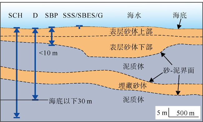
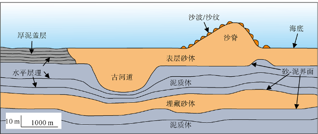
图2 研究区海砂砂体垂向分布及使用的研究方法示意图蓝色标记表示研究方法获取地层信息的范围。SCH为单道地震、SBP为浅地层剖面、SSS为侧扫声呐、SBES为单波束测深、G为抓斗取样、D为地质钻探。浅地层剖面对砂层的穿透厚度小于10m。表层砂体分为上部和下部 Fig. 2 Vertical distribution of marine sand-gravel body and research methods used in the study area. The blue mark represents the extent to which stratigraphic information was obtained by the study method. SCH: single-channel seismic; SBP: sub-bottom profiler; SSS: side-scan sonar; SBES: single-beam echo-sounder; G: grab sampling; and D: geological drilling. The penetration thickness of the sub-bottom profile to sand and gravel is less than 10 m. The surface sand-gravel body is divided into upper and lower parts |
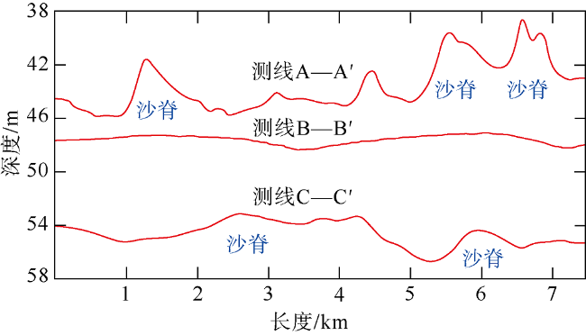
图3 研究区典型水深剖面揭示的地形特征红色线为A—A′、B—B′、C—C′ 3条典型测线的水深变化, 测线位置见 Fig. 3 Topographic features in the study area revealed by typical depth profiles. The red line indicates water depth changes of the survey lines A-A′, B-B′, and C-C′, and the locations of the survey lines are shown in |
图4 侧扫声呐揭示海底地貌特征a. 研究区测线分布情况; b、c、e. 海底沙波脊线走向; d. 研究区中部平坦的海底地形; f. 交错的海底拖痕; g. 叠置在沙波之上的沙纹微地貌 Fig. 4 Side-scan sonar revealing seafloor geomorphic features. (a) shows the distribution of survey lines in the study area; (b), (c), and (e) reveal the strike of sand wave ridges; (d) reveals the flat seabed topography in the middle of the study area; (f) reveals the intersecting seafloor trawling marks; and (g) reveals the sand ripples superposed on the sand waves |
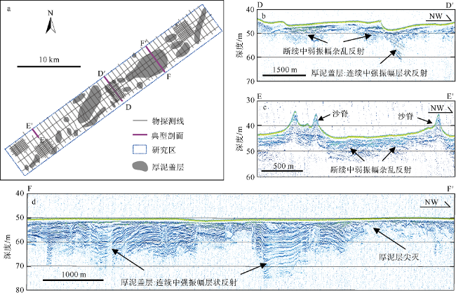
图5 浅地层剖面揭示厚泥盖层分布和表层砂体特征a. 厚泥盖层平面分布; b. 厚泥盖层与表层砂体的渐变交错; c. 海底沙脊附近表层砂体的特征; d. 厚泥盖层厚度的变化和特征 Fig. 5 Sub-bottom profile revealing the characteristics of thick argillaceous overlying strata and the distribution of the surface sand-gravel body. (a) shows the distribution of thick argillaceous overlying strata, (b) indicates the gradual interchange between thick argillaceous overlying strata and the surface sand-gravel body, (c) displays the characteristics of the surface sand-gravel body near submarine sand ridge, and (d) gives the characteristics and variation of thick argillaceous overlying strata |
图6 表层和埋藏砂体的特征a. 单道地震剖面揭示的砂体地震响应特征, U1~U4为识别的地震层序单元, R0~R3为主要地震反射界面; b. 图a的描图, 揭示表层砂体(对应U1)、埋藏砂体(U3)以及泥质体(U2、U4), 埋藏砂体中还可见层状的不利砂体发育区; 蓝色虚线为砂-泥突变界面(对应R1~R3), 黑色虚线为表层砂体上部(U1-1)和下部(U1-2)的分界面; c. 浅地层剖面揭示表层砂体上部的特征, 是对单道地震剖面中表层砂体地震特征的补充 Fig. 6 Characteristics of surface and buried sand-gravel bodies. (a) shows seismic response characteristics of the sand-gravel body revealed by single-channel seismic profile. U1~U4 are identified seismic sequence units. R0~R3 are the main seismic reflection interfaces. (b) is a drawing of (a), revealing the surface sand-gravel body (corresponding to U1), buried sand-gravel body (U3) and mud body (U2 and U4). There are also areas in the buried sand bodies that are not suitable for the occurrence of sand bodies. The blue dashed line is the sand-mud interface (corresponding to R1~R3), and the black dashed line is the interface between the upper (U1-1) and lower (U1-2) surface sand-gravel bodies. (c) Sub-bottom profiles reveal the characteristics of the upper surface sand body, which is a supplement to the seismic characteristics of the surface sand body in the single-channel seismic profile |
表2 海砂砂体的地震层序单元划分和响应特征Tab. 2 Seismic sequence unit division and seismic response characteristics of marine sand body |
| 地震层序单元 | 地震响应特征 | 指示沉积类型 | |
|---|---|---|---|
| U1 | U1-1 | 连续性好、强振幅、低频平行层状反射 | 表层砂体上部 |
| U1-2 | 连续性差、弱振幅、夹杂空白或杂乱的反射 | 表层砂体下部 | |
| U2 | 连续性好、强振幅、平行层状反射 | 泥质体 | |
| U3 | 连续性差、弱振幅、夹杂空白或杂乱的反射 | 埋藏砂体 | |
| U4 | 连续性好、强振幅、平行层状反射 | 泥质体 | |
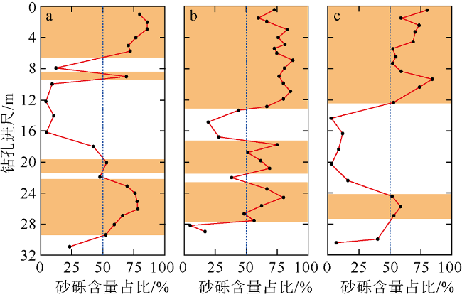
图7 过测线G—G′的3个钻孔砂砾含量占比及砂体层位分布a、b、c分别为ZK1、ZK2、ZK3 3个钻孔岩心的数据。黑色点为取样点及测试结果, 红色线为测试结果的连线。黄色块为砂体的赋存层位; 白色块为泥质体的赋存层位 Fig. 7 Sand and gravel content ratio and sand body location distribution of the three boreholes along the survey line G—G′. (a), (b), and (c) are the data of cores ZK1, ZK2, and ZK3, respectively. The black dots are the sampling points and test results, and the red lines are the connecting lines of the test results. The yellow shading block is the stratigraphic position of the sand body; and the white block is the stratigraphic position of argillaceous bodies |
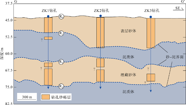
图8 钻孔揭示的砂体层位与单道地震识别的砂体对比深黄色方块为钻孔揭示的砂体层位; 浅黄色块和灰色块分别为单道地震识别的砂体和泥质体。R0~R3为主要地震反射界面 Fig. 8 Comparison of sand body stratigraphic position revealed by borehole and sand body identified by single-channel seismic. The dark yellow block is the sand and gravel layer revealed by the borehole. The light yellow block and the gray block are the sand-gravel body and argillaceous body identified by single-channel seismic respectively. R0~R3 are the main seismic reflection interface |
表3 研究区有利海砂赋存的地貌标志及地球物理特征Tab. 3 Geophysical characteristics and favorable occurrence signs of marine sand bodies in the study area |
| 物探方法 | 指示砂体 | 有利赋存标志 | 地球物理特征 |
|---|---|---|---|
| 单波束测深 | 平面分布 | 海底沙脊 | 沙脊形态呈槽脊相间的波状起伏, 总体顺潮流方向呈条带状展布。沙脊上发育叠置大型沙波 |
| 侧扫声呐 | 平面分布 | 海底沙波、沙纹 | 沙波脊线两侧回波强度变化明显, 总体近垂直于潮流方向呈条带状展布, 波形不对称。沙波上发育叠置的小沙波、沙纹等微地貌。反映了沉积物供应充足 |
| 浅地层剖面 | 平面分布、表层砂体上部 | 无厚泥盖层 | 砂层穿透小于10m, 为断续的中弱振幅杂乱反射, 无明显层状反射, 指示浅部较厚的砂质底质, 利于砂体赋存。泥层穿透大于10m, 为连续性好的中强振幅高频层状反射, 成层性明显, 指示为泥质盖层, 不利于砂体赋存 |
| 单道地震 | 表层及埋藏砂体 | 埋藏古河道 | 埋藏古河道呈U型反射结构, 充填物呈杂乱反射, 利于砂体赋存。砂体出现“白雾”, 即连续性差的弱振幅反射中夹杂空白、杂乱的反射 |
| [1] |
曹欣中, 1985. 浙江近海沿岸上升流与渔场的关系[J]. 海洋湖沼通报, (1):25-28.
|
| [2] |
曹雪晴, 谭启新, 张勇, 等, 2007. 中国近海建筑砂矿床特征[J]. 岩石矿物学杂志, 26(2):164-170.
|
| [3] |
杜晓琴, 李炎, 高抒, 2008. 台湾浅滩大型沙波、潮流结构和推移质输运特征[J]. 海洋学报, 30(5):124-136.
|
| [4] |
冯京, 褚宏宪, 杨源, 等, 2011. 浅地层剖面测量在海砂资源调查中的应用[M]//中国地球物理学会. 中国地球物理·2011. 合肥: 中国科学技术大学出版社: 709.
|
| [5] |
郭婷婷, 高文洋, 高艺, 等, 2010. 台湾海峡气候特点分析[J]. 海洋预报, 27(1):53-58.
|
| [6] |
李立, 郭小钢, 吴日升, 2000. 台湾海峡南部的海洋锋[J]. 台湾海峡, 19(2):147-156.
|
| [7] |
李勇航, 单晨晨, 苏明, 等, 2020. 声学水面无人艇在浅水海底地貌调查中的应用[J]. 海洋地质与第四纪地质, 40(6):219-226.
|
| [8] |
刘振夏, 1996. 中国陆架潮流沉积研究新进展[J]. 地球科学进展, 11(4):414-416 (in Chinese).
|
| [9] |
刘振夏, 夏东兴, 2004. 中国近海潮流沉积沙体[M]. 北京: 海洋出版社: 176.
|
| [10] |
罗昆, 刘刚, 薛玉龙, 等, 2017. 利用单道地震反射数据预测海南岛东部近海砂层分布[J]. 海洋地质与第四纪地质, 37(1):125-130.
|
| [11] |
倪玉根, 何健, 习龙, 等, 2019-09-06. 一种盖层海砂泥砂层分界面的物探识别和找砂方法: 中国, 110208855A[P] (in Chinese).
|
| [12] |
倪玉根, 李建国, 习龙, 2021. 海砂粒级划分标准和沉积物命名方法探讨[J]. 热带海洋学报, 40(3):143-151.
|
| [13] |
洪华生, 丘书院, 阮五崎, 等, 1991. 闽南—台湾浅滩渔场上升流区生态系研究概述[M]//闽南—台湾浅滩渔场上升流区生态系研究. 北京: 科学出版社, 1-17(in Chinese).
|
| [14] |
谭启新, 孙岩, 1988. 中国滨海砂矿[M]. 北京: 科学出版社: 100-103(in Chinese).
|
| [15] |
谭启新, 1998. 中国的海洋砂矿[J]. 中国地质, (4):23-26.
|
| [16] |
王圣洁, 刘锡清, 李学杰, 等, 1997. 滨、浅海沉积砂砾石资源的利用潜力[J]. 海洋地质动态, (11):2-4 (in Chinese).
|
| [17] |
张金鹏, 万荣胜, 朱本铎, 2014. 中国近海砂矿资源开发与利用及相关战略建议[J]. 矿床地质, 33(S1):879-880 (in Chinese).
|
| [18] |
赵铁虎, 张训华, 王修田, 等, 2007. 广东珠江口—东平近海浅地层剖面的声学特征及地质意义[J]. 物探化探计算技术, 29(3):183-188.
|
| [19] |
赵铁虎, 李军, 张异彪, 等, 2011. 舟山海域海砂资源声地层剖面探测研究[J]. 物探化探计算技术, 33(3):340-345.
|
| [20] |
中国地质调查局, 2012. DD2012-10 海砂(建筑用砂)地质勘查规范[S] (in Chinese).
|
| [21] |
|
| [22] |
|
/
| 〈 |
|
〉 |


